
Choosing the wrong pipe diameter is one of the most expensive mistakes in a compressed air system. A pipe that is too small causes pressure drop. Your compressor then works harder, your tools underperform, and your energy bill climbs.
This guide gives you a compressed air pipe size chart you can use straight away. It matches airflow (CFM), pipe length, and pipe diameter. It also explains how the chart works, so you can adapt it to your own plant.
Why Compressed Air Pipe Size Matters
Compressed air loses pressure as it travels through a pipe. The smaller the pipe and the longer the run, the bigger the loss. Every unnecessary 1 bar (14.5 psi) of pressure drop can add roughly 6–8% to compressor energy use, because the compressor has to run at a higher discharge pressure to compensate.
The right size gives you:
- Stable pressure at the point of use
- Lower energy consumption
- Less strain on the compressor
- Room to expand later
For a deeper look at the basics, read our air pipe sizing guide.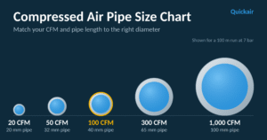
What You Need Before Using the Chart
Collect three numbers first:
- Airflow demand (CFM): Add up the air consumption of all tools and machines that run at the same time. Add 20–25% for future growth. If you are unsure how to calculate it, see our guide to calculating compressed air flow.
- Pipe length: Measure the longest run from the compressor or receiver to the farthest point of use.
- Working pressure: The chart below assumes about 7 bar (100 psi), which suits most industrial plants.
Compressed Air Pipe Size Chart (Based on Flow and Length)
The table shows the minimum recommended inside pipe diameter to keep pressure drop at or below 0.1 bar (about 1.5 psi) in the main line.
| Airflow (CFM) | Airflow (m³/h) | 30 m (~100 ft) | 50 m (~165 ft) | 100 m (~330 ft) | 200 m (~660 ft) | 300 m (~1000 ft) |
|---|---|---|---|---|---|---|
| 20 | 34 | 20 mm (¾″) | 20 mm (¾″) | 20 mm (¾″) | 25 mm (1″) | 25 mm (1″) |
| 50 | 85 | 25 mm (1″) | 25 mm (1″) | 32 mm (1¼″) | 32 mm (1¼″) | 32 mm (1¼″) |
| 100 | 170 | 32 mm (1¼″) | 32 mm (1¼″) | 40 mm (1½″) | 50 mm (2″) | 50 mm (2″) |
| 150 | 255 | 32 mm (1¼″) | 40 mm (1½″) | 50 mm (2″) | 50 mm (2″) | 65 mm (2½″) |
| 200 | 340 | 40 mm (1½″) | 40 mm (1½″) | 50 mm (2″) | 65 mm (2½″) | 65 mm (2½″) |
| 300 | 510 | 50 mm (2″) | 50 mm (2″) | 65 mm (2½″) | 80 mm (3″) | 80 mm (3″) |
| 500 | 850 | 65 mm (2½″) | 65 mm (2½″) | 80 mm (3″) | 80 mm (3″) | 100 mm (4″) |
| 750 | 1,274 | 65 mm (2½″) | 80 mm (3″) | 100 mm (4″) | 100 mm (4″) | 100 mm (4″) |
| 1000 | 1,699 | 80 mm (3″) | 80 mm (3″) | 100 mm (4″) | 100 mm (4″) | 125 mm (5″) |
How to read it: Find your CFM in the left column, move across to your pipe length, and read off the diameter. If your numbers fall between two rows, choose the larger size.
Pipe Diameter for 100 CFM
This is one of the most common questions we hear. For 100 CFM at 7 bar:
- Up to 50 m: 32 mm (1¼″) pipe
- Around 100 m: 40 mm (1½″) pipe
- 200 m and beyond: 50 mm (2″) pipe
If you expect to add machines later, go up one size now. It costs far less than re-piping later.
Quick Reference: Pipe Size by Flow Only
For a rough estimate when you do not have the pipe length yet:
| Flow (CFM) | Typical pipe size |
|---|---|
| Up to 25 | 20 mm (¾″) |
| 25–60 | 25 mm (1″) |
| 60–120 | 32–40 mm (1¼″–1½″) |
| 120–250 | 40–50 mm (1½″–2″) |
| 250–400 | 50–65 mm (2″–2½″) |
| 400–700 | 65–80 mm (2½″–3″) |
| 700–1200 | 80–100 mm (3″–4″) |
Allow for Fittings, Bends and Valves
Every elbow, tee, and valve adds resistance, like extra pipe length. Add an equivalent length for each fitting before you use the chart. As a rule of thumb, a 90° elbow adds about 1–1.5 m of equivalent length in small pipes and more in large ones.
This is where modular aluminium piping helps. Smooth internal walls and fewer, better-designed fittings keep pressure drop low. Read more in our aluminium vs steel piping comparison.
5 Common Sizing Mistakes to Avoid
- Sizing for today only. Plants grow. Leave 20–25% spare capacity.
- Ignoring the longest run. Size for the farthest point, not the nearest one.
- Using the same diameter everywhere. Use a larger main header and smaller drops to machines.
- Forgetting fittings. A pipe that looks fine on paper can fail once every bend is counted.
- Accepting leaks as normal. Leaks make a correctly sized pipe behave like an undersized one. See our guide to compressed air leak detection.
Pipe Material Affects the Result
The chart uses inside diameter, so material matters. Steel and iron pipes rust and scale, which narrows the bore over time. Aluminium stays smooth and corrosion-resistant, so the size you choose today performs the same in ten years. Learn more about corrosion-resistant piping.
Frequently Asked Questions
What size pipe do I need for 100 CFM?
For runs up to 50 m at 7 bar, a 32 mm (1¼″) pipe works. For about 100 m, use 40 mm (1½″). For longer runs, use 50 mm (2″).
What is the acceptable pressure drop in a compressed air pipe?
Aim for no more than 0.1 bar (about 1.5 psi) in the main line. The total drop from compressor to point of use should stay under about 0.5 bar (7 psi), or about 10% of working pressure.
Does pipe length affect pipe size?
Yes. The longer the run, the larger the diameter needed to keep pressure drop in check.
Is bigger always better?
Larger pipe lowers pressure drop but costs more upfront. Size for your actual demand plus 20–25% growth.
Should I size the pipe by inside or outside diameter?
Always use the inside diameter, because that is what airflow depends on. Check the manufacturer’s actual bore when you choose a modular system.
Get the Right Size the First Time
Every plant layout is different, and this chart is a strong starting point. For a system designed around your exact demand, our team at Quickair can size and plan a modular aluminium compressed air network for you.